Rim Board Design and Installation Guide – United States
Introduction
This document presents general information about designing buildings where TECO certified rim boards are used as part of the framing. It provides general information about the intended uses of rim boards, installation of the product, and some acceptable building practices when rim boards are used in light-framed wood structures. It is not intended to be an entirely comprehensive document or cover all possible uses of rim board and it may not apply if rim board is used for other purposes. All rim board is not a direct substitute for structural composite lumber, despite the fact that SCL may be used to make rim board. Consult TECO at www.tecotested.com for clarification of any information presented in this document.
Product Description and Intended Uses
A rim board is a structural element installed around the perimeter of floor framing that closes the ends of joists and performs the tasks of transferring vertical and horizontal loads to structural wall components below. The solid rectangular profile throughout its depth allows rim board to serve as an attachment surface for sheathing, weather barriers, siding and deck ledger boards, etc. Rim board is made from engineered wood products like OSB, plywood or structural composite lumber and are most commonly used in floor systems that are framed with I-joists. Because it is an engineered wood product, rim board can be manufactured in a variety of standard depths (Table 1) that match the depth of I-joists used to frame the rest of the floor system.
TECO defines two grades of rim board in RB 133 Rim Board Product Standard, they are Standard and Performance. While both grades can be used to span openings in a foundation or over a wood-framed wall system, the Performance grade has higher design values and is suited for use in applications where greater strength is required. Proper nailing of the floor sheathing to the tops of the structural floor joists and the rim board, and proper attachment of the rim board to the framing below, results in individual structural elements that work together as a structural floor system.
Table 1. Common dimensions of Rim Board
Thickness (in)
1, 1⅛, 1¼, 1½
Depth (in)
9½, 11⅞, 14, 16, 18, 20, 22, 24
Length (ft)
8 to 24
Identification of Certified Products
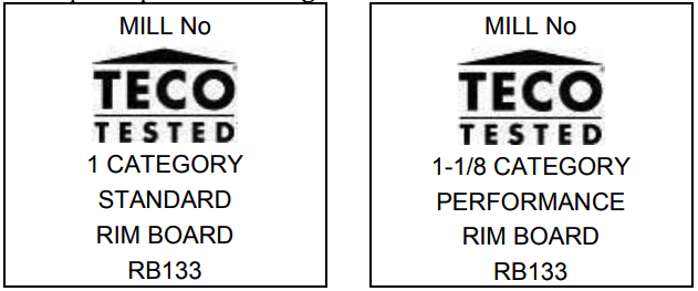
TECO certified rim board must be identified with the following information:
Name of the manufacturer or the TECO mill number (posted on TECO's web site);
TECO's registered Certification Mark;
Grade of the rim board;
Performance Category;
Thickness; and
The RB 133 standard.
Figure 1. Example Gradestamps for TECO certified rim board.
Installation Instructions
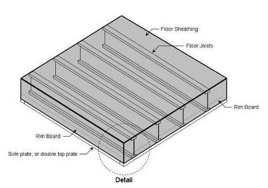
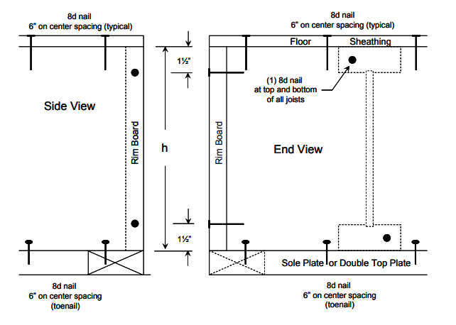
Floor systems can only achieve their full structural capacity with proper installation of all structural elements. This means using appropriately-sized nails and following recommended nailing schedules. Table 2304.9.1 of the International Building Code (2012) provides nailing schedules for all structural elements in building construction. Figure 2 shows the primary structural elements involved when installing rim board: (1) floor sheathing to rim board, (2) rim board to floor joists, (3) rim board to rim board corner details, (4) rim board to sole plate, and (5) deck ledgers to rim board.
Figure 2. Structural floor system shown with rim board.
Floor sheathing to Rim Board
Minimum 8d nails, spaced 6-inches on center, are required for attachment of floor sheathing to the top edge of the rim board. These nail connections provide resistance to the lateral loads from the wall.
Rim Board to I-joist
Use two (2) 8d nails, one each into the top and bottom flanges. This is typical for rim board having a thickness up to 1⅛ inches. A larger nail size may be required by the I-joist manufacturer for use with thicker rim boards. These nail connections provide lateral support for the floor joists to resist rotation.
Rim Board to Rim Board
Use a minimum of two (2) 8d nails to attach rim board to rim board at corner details (Figure 3). Rim board to rim board butt joints should be made between floor joists to minimize damage to joists caused by end nailing.
Rim Board to Sole plate
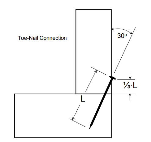
Toe nail using 8d nails, spaced 6-inches on center; or 16d nails, spaced 12-inches on center. The toe-nailing details should follow recommendations published in section 11 of the National Design Specifications for Wood Construction (ANSI/AWC, 2012), as shown in Figure 4.
Figure 3. Nailing schedule for Detail area in Figure 2.
Attachment of Siding and Deck Ledgers to Rim Board
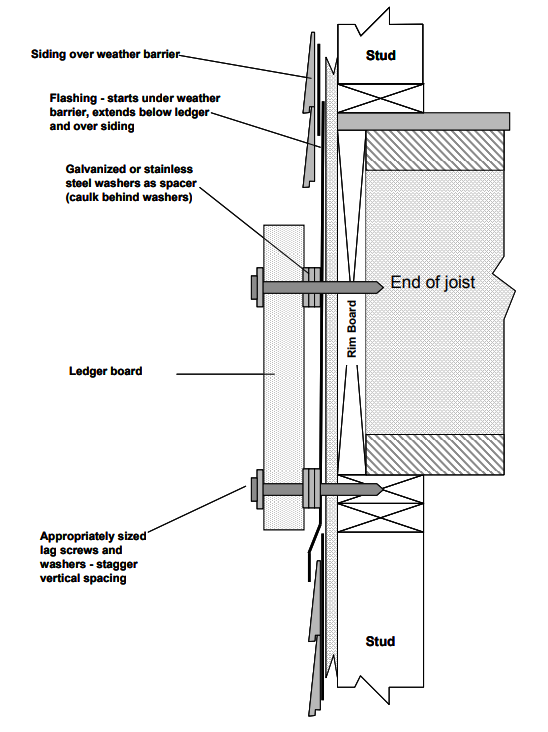
Rim board can provide an attachment base for siding and/or an exterior deck ledger. For deck ledger attachment, Table 11J of the National Design Specifications for Wood Construction (ANSI/AWC, 2012) provides reference lateral design values for lag screws. For ½" diameter lag screws, a minimum penetration of 8 times the diameter, or 4-inches, provides 350 lbf of lateral resistance per fastener, based on the use of a species having a specific gravity of at least 0.42. The ANSI/AWC standard should be used for designing the fasteners for other species, and other lag screw sizes. Construction details that avoid potential decay and situations should be used, such as providing air space between the deck ledger and the rim board by use of stainless steel washers as spacers (Figure 5).
Figure 5. Sliding and deck ledger attachment to rim board
Design Capacities for Rim Board
Rim board recognized in accordance with TECO RB133 is available in sizes listed in Table 1 and hasdesign capacities listed in Tables 2 and 3.
Table 2. Design capacities for rim board
Rim Board Grade
Performance Category
H1 (lb/ft)
V1 (lb/ft)
Z1 (lb)
P1 (lb)
Depth (d) Limitation (in)
d ≤ 24
D ≤ 16
16 ≤ d ≤ 24
D ≤ 24
d ≤ 24
Standard
1
180
3,300
1,650
300
3,500
1⅛
180
4,400
3,000
350
3,500
Performance
1⅛
200
4,850
3,200
350
3,500
1. H is horizontal shear load transfer; V is bearing (vertical) load; Z is lateral resistance of 13mm diameter lag screw; and P is concentrated vertical load capacity.
Table 3. Allowable edgewise bending properties for rim board used as lintels when the span does not exceed 4-ft1,2
Grade
Fbe (lb/in²)1
Ee (lb/in²)1
Fve (lb/in²)1
Fc⊥e (lb/in²)1
Standard, Performance
600
550,000
270
550
1. Fbe is allowable edgewise bending stress, Ee is allowable edgewise modulus of elasticity; Fve is allowable edgewise shear stress; and Fc⊥e is allowable compression perpendicular to grain.
2. Values are applicable to long-term duration (10 years), and can be adjusted for other load durations in accordance with applicable design codes (except for edgewise modulus of elasticity and compression perpendicular to grain).
Design Procedures
When rim board is used to span openings up to 4-ft in length, allowable loads are calculated based on design calculations that check for bending, shear, and bearing. Table 4 provides allowable loads based on the design values in Tables 2 and 3.
Several loading scenarios may occur that are outside the scope of this guide. For example, when rim board is used in applications requiring a high lateral load transfer capacity, specialty connectors can be used between the rim board and framing (or sole plate). Consult a structural engineer to determine the additional load transfer capacity needed, and install specialty connectors that provide the added lateral load transfer capacity.
Rim boards can also be used as fire blocking panels. Section 717.2.1 of the International Building Code states that fire blocking can consist of one thickness of 23/32" wood structural panel with joints backed by 23/32" wood structural panel. Rim board thickness of 1" and 1⅛" thickness exceeds the minimum requirements.
Rim board can be subjected to a combined uniform and concentrated vertical load. For this scenario, the structural engineer should check that the applied concentrated load does not exceed the concentrated load capacity (P) provided in Table 2. Additionally, the bearing capacity of this load scenario should be checked by combining the applied uniform load and the equivalent uniform load created by the applied concentrated load. The equivalent uniform load should be based on the bearing length of the applied concentrated load, and increased by a 45° load distribution path from the floor sheathing down to the rim board. The calculated combined uniform load is then compared to the allowable vertical load capacity (V) from Table 2.
Table 4. Design capacities – allowable loads for rim boards used as headers in the US.
Performance Category
Depth (in.)
Rim Board Span2 (in.)
24
30
36
42
48
Allowable Load3 (lb/ft)
1
9½
1,656
1,175
867
661
519
11⅞
1,656
1,656
1,255
975
775
14
1,656
1,656
1,613
1,276
1,075
16
1,656
1,656
1,613
1,276
1,276
1-1/8
9½
1,862
1,322
975
744
584
11⅞
2,514
1,862
1,412
1,097
872
14
2,514
1,862
1,412
1,435
1,155
16
2,514
1,862
1,412
1,435
1,435
1. This table is for preliminary design only. Final design should include a complete analysis, including bearing stresses and lateral stability.
2. Span is distance between edges of opening. No joints in rim board are allowed in opening, or within 12" of opening.
3. Calculated values are worst case governed by bending, shear, or deflection, and vertical bearing load.