
Who We Are
We offer TIC services to enhance fire, life, and electrical safety globally, confirming compliance and reducing risks.

NFPA Global Solutions marks signify safety and quality, confirming products meet rigorous standards and build market trust.
A client portal is a secure online space where clients can access services, documents, and support easily.
NFPA Global Solutions marks signify safety and quality, confirming products meet rigorous standards and build market trust.
Get free foam, antifreeze, dry chemical, and standard sprinkler kits with shipping in the U.S. Specify quantity needed.
Version 2.3 · October 1, 2013 · Timberco Inc. dba TECO
The purpose of this standard is to provide a method for judging the acceptance of wood-based materials for use as rim board in wood-framed construction in the United States and Canada. It establishes performance criteria for two grades of rim board, "Standard" and "Performance". Minimum requirements for quality assurance and third-party inspection are included.
This Standard applies to rim boards made from wood based panels, produced in minimum lengths of 8-feet (2.44 m), minimum thicknesses of 1 inch (25.4 mm) and maximum of 1¼ inches (31.8 mm), and maximum depths of 24 inches (610 mm). It applies to rim boards that are intended to be fully supported along their bearing length and those that can be used as headers to span wall openings of 4-feet (1.22 m) or less.
For purposes of this standard, the primary units of measurement follow the English Customary system. Metric equivalent values are provided in parentheses to facilitate the certification of products intended for use in Canada.
Rim board is a general term used to describe the structural wood-based building material that:
TECO certified rim board is available in two grades:
Rim board qualified to this standard must be composed of wood, and may be in the form of oriented strand board1, plywood2 or other composite structural panels. Oriented strand lumber or laminated veneer lumber manufactured in accordance with ASTM D5456 is also acceptable.
Rim board qualified to this standard shall be manufactured to the following depth and thickness tolerances:
1 The base OSB panel must be qualified to PS2 or CSA O325.
2 Plywood must meet the requirements of PS1 or CSA O151.
Material for qualification must be sampled according to the requirements set forth in this section. Samples must be selected and labeled by a TECO representative or a representative of a TECO approved ISO/IEC 17025 accredited lab or ISO/IEC 17020 accredited inspection body. The following quantities of material must be submitted:
Samples shall be appropriately identified, labeled and packaged for shipment to the designated TECO laboratory by the representative of the sampling organization, or supervised by such representative.
(A) Test Specimens
(B) Test Method
(C) Performance Criteria
(A) Test Specimens
(B) Test Method
(C) Performance Criteria
(A) Test Specimens
(B) Test Method
(C) Performance Criteria
(A) Test Specimens
(B) Test Method
(C) Performance Criteria
(A) Test Specimens
(B) Test Method
(C) Performance Criteria
(A) Test Specimens
(B) Test Method
(C) Performance Criteria
(A) Test Specimens
(B) Test Method
(C) Performance Criteria
| Rim Board Grade | Minimum thickness (inch) | H (lbf/ft) | V (lbf/ft) | Z (lbf) | P (lbf) | |
|---|---|---|---|---|---|---|
| d ≤ 24 | d ≤ 16 | 16 ≤ d ≤ 24 | D ≤ 24 | d ≤ 24 | ||
| Standard | 1 | 505 | 9900 | 4950 | 1200 | 10,500 |
| 1-1/8 | 505 | 13,200 | 9000 | 1400 | 10,500 | |
| Performance | 1 | N/A3 | ||||
| 1-1/8 | 560 | 14,550 | 9600 | 1400 | 10,500 | |
For SI: 1 lb/ft = 14.594 N/m; 1 lbs = 4.448 N; 1 inch = 25.4 mm.
1. Gross adjustment factors provided in Appendix 1 for determining allowable design values.
2. H is horizontal shear load transfer; V is bearing (vertical) load; Z is lateral resistance of ½-inch diameter lag screw; and P is concentrated vertical load.
3. The minimum thickness for Performance grade rim board is 1-1/8 inch.
| Grade | fbe (lbf/in²) | Ee (lbf/in²) | fve (lbf/in²) | Fc⊥e (lbf/in²) |
|---|---|---|---|---|
| Standard, Performance | 2070 | 580,000 | 850 | 920 |
For SI: 1 lb/in² = 6.895 kPa.
1. All tests are loaded edgewise. fbe is edgewise modulus of rupture, Ee is edgewise modulus of elasticity, fve is edgewise shear, and Fc⊥e is edgewise compression perpendicular to grain at 0.04-inch deformation.
2. Values are applicable to standard-term duration (10 years), and can be adjusted for other load durations in accordance with applicable design codes (except for edgewise modulus of elasticity and compression perpendicular to grain).
| Component | Thickness | Depth or Width | Length |
|---|---|---|---|
| Rim board | As required for each applicable test that utilizes the assembly | As required for each applicable test that utilizes the assembly | Minimum 36 inch |
| I-joist1 | Maximum 1¾ inch | Minimum 9¼ inch | 12 inch |
| Sheathing | Minimum 7/16 inch OSB | 12 inch | Minimum 39 inch |
| Sill Plate (spruce-pine-fir grade) | Nominal 2 inch lumber | Nominal 4 inch lumber | Minimum 39 inch |
For SI conversions, 1 inch = 25.4 mm. 1. Part of assembly construction (not rim board).
| Component | Thickness | Depth or Width | Length |
|---|---|---|---|
| Rim board | Minimum of 25.4 mm | Maximum of 600 mm | 900 mm |
| I-joist1 | Maximum 38 mm flange | Maximum of 600 mm | 300 mm |
| Sheathing | 15.8 mm | 300 mm | Minimum of 975 mm |
| Sill Plate (spruce-pine-fir grade) | 38 mm | 89 mm | Minimum of 975 mm |
| Connected Elements | Fastener Specification and Spacing1,2 – US | Fastener Specification and Spacing2,3,4 – Canada |
|---|---|---|
| Sheathing to rim board and joist | 8d nails, spaced 6 inches on center | 51mm nails spaced 150mm on center |
| Bottom plate (from above) through subfloor to rim board2 | Not applicable | 82 mm nails spaced 400 mm on center |
| Rim board to sill plate | 8d nails, spaced 6 inch on center | Toe-nail two (2) 63.5 mm nails through joist into sill plate, spaced 150mm on center |
| I-joist to sill plate | Use 2 8d nails | Use two (2) 63.5 mm nails |
| Rim board to I-joist | Use 2 8d nails | Use two (2) 63.5 mm nails |
1. Box nails. 2. Alternative nailing schedules may be specified as long as they meet the minimum requirements. 3. Common or spiral nails as per the National Building Code of Canada. 4. Nails through bottom plate (from wall above) must be used when testing rim board for approval in Canada and are used to verify the risk of splitting.
(A) Test Specimens
(B) Test Method
(C) Performance Criteria
(A) Test Specimens
(B) Test Method
(C) Performance Criteria
(A) Test Specimens
(B) Test Method
(C) Performance Criteria
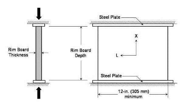
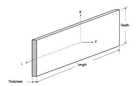
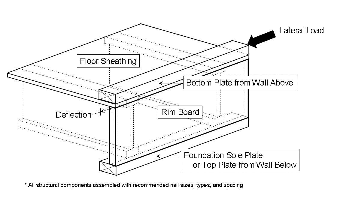
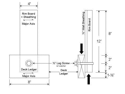
When rim board is manufactured from structural use panels such as plywood, OSB or other similar materials, control values and specifications stemming from the product standards must be established as follows.
(A) Rim board based on OSB and composite veneer/OSB panels (PS 2-type panels)
A mill specification with control values shall be developed in accordance with the following requirements using the same panels for each thickness evaluated in Sections 3.2 through 3.4:
(B) Rim board based on structural plywood
A mill specification for each rim board thickness evaluated in Sections 3.2 through 3.4 shall be developed for species, thickness, and panel grade in accordance with PS 1.
Control values for oriented strand lumber (OSL), laminated strand lumber (LSL), laminated veneer lumber (LVL), and other similar structural composite lumber products shall be established in accordance with ASTM D 5456.
In order for a manufacturer to use the TECO TESTED® certification mark, it must agree to follow TECO's quality control policies in this section and as referenced.
A manufacturer of certified rim board shall develop a quality control manual that satisfies the requirements of the TECO Inspection Procedure – SUP Sections 3.2.1 and 3.2.2. The QC manual shall establish the methods the manufacturer will follow to maintain conformance with the mill specification and control values established according to Section 3.5 and maintain performance levels at or above the design capacities. Certified rim board shall be manufactured in accordance with the QC manual.
Manufacturers of TECO certified rim board shall be audited a minimum of four times per year, approximately quarterly, for operation in accordance with their quality control manual. Audit frequencies shall be assigned in accordance with TECO Inspection Procedure – SUP Sections 3.2.3 and 4.1.
TECO will conduct periodic product testing for evaluation against requirements given in Sections 3.2 through 3.4. The frequency, not to exceed quarterly, and type of testing will depend on several factors including TECO quality system audit findings, product history, variability within the product, and production volume.
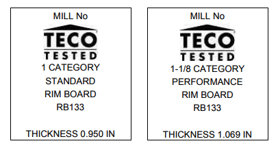
TECO certified rim board must be identified with the following information:
Example gradestamps are presented in Figure 5.
Allowable design capacities (F) are derived by dividing the population characteristic ultimate load values by adjustment factors that account for safety and probability of failure levels used for design. The population characteristic value commonly used for structural wood products is the 5th percentile at 75% confidence, and the adjustment factor of 2.1 is commonly used for strength properties of structural wood products.
The general equation for calculating the allowable design capacity of wood products is:
Where F = allowable property for an estimated 10-year load duration; P.05 = Characteristic value, equals the lower 5th percentile of test data (10-minute duration of load); 2.1 = Adjustment factor that converts Characteristic Value to Allowable Value. The adjustment factor includes a 10-year duration of load factor of 1.6 and a safety factor of 1.3.
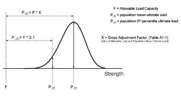
In section 3, qualification testing and performance requirements are based on small sample sizes (n), and involve calculation of the sample mean ultimate load (p.50). To determine allowable load from mean values from qualification test data, the relationship is:
where X = gross adjustment factor relating allowable load (F) to population average ultimate load (P.50). Setting equations [A-1] and [A-2] equal:
Using the relationship between population mean and population 5th percentile:
where 1.645 = the population one-sided tolerance limit for calculating 5th percentile assuming large sample size and normal distribution; COV = population coefficient of variation. Substituting [A-4] into [A-3]:
Solving for X:
Because performance tests in section 3 are based on small sample sizes, equation [A-6] is modified to accept a one-sided tolerance limit for small sample sizes. The resulting gross adjustment factor equation is:
where k.05,.75 = 5th percentile at 75% confidence one-sided tolerance limit for sample size n (ASTM D2915, Table 3).
Substitution of sample mean ultimate load (p.50) and equation [A-7] into equation [A-2] results in equation [A-8]. Note that coefficient of variation for small sample sizes would be large, and would result in an overly-conservative calculated allowable property (F). For this reason, the population coefficient of variation (COV) remains in equation [A-4]. When using performance test results on smaller sample sizes:
Table A1-1 provides values needed for determining the adjustment factor X, for calculating allowable properties using section 3 performance test results. Determine the capacity as the mean test value divided by Gross Adjust Factor, and is applicable to a shallower rim board of the same thickness and species combination. Table A1-2 presents the minimum Allowable Stress Design Values for rim boards qualified to this standard.
| Allowable Property | Gross Adjustment Factor, X | Sample size (n) | k.05,.75,n | Assumed Population COV | Adjustment factor, C |
|---|---|---|---|---|---|
| Vertical Uniform Load Transfer (V) (§3.2.1) | 3.0 | 10 | 2.104 | 0.14 | 2.1 |
| Lateral Load Transfer (H)1 (§3.2.2) | 2.8 | 10 | 2.104 | 0.12 | 3.0 |
| Concentrated Load Transfer (P) (§3.2.3) | 3.0 | 10 | 2.104 | 0.14 | 2.1 |
| Edgewise Bending (F) (§3.2.4) | 3.452 | 28 | 1.879 | 0.21 | 2.1 |
| ½" dia. Lag Screw Lateral Resistance3 (Z) (§3.3.1) | 4.0 | 10 | 2.104 | 0.12 | 3.0 |
1. H is a wood-framed system, however, assumed COV is for rim board product. Safety Factor is a calculated value that results in a gross adjustment factor of 3.0.
2. Note that the Gross Adjustment Factor (X) incorporates adjustment factors for volume (1.45), center-point loading (1.08), and moisture (1.05).
3. Capacities for the following items shall be determined according to ICC-ES AC 47, or the NDS, as applicable: connection of the top edge of the rim board to the building diaphragm; attaching the rim board to the wall plate below; attaching the rim board to the I-joists; attaching the exterior siding to the rim board; attaching an exterior deck ledger.
| Rim Board Grade | Minimum thickness (in) | H1 (lb/ft) | V1 (lb/ft) | Z1 (lb) | P1 (lb) | |
|---|---|---|---|---|---|---|
| d ≤ 24 | D ≤ 16 | 16 ≤ d ≤ 24 | D ≤ 24 | d ≤ 24 | ||
| Standard | 1 | 180 | 3,300 | 1,650 | 300 | 3,500 |
| 1⅛ | 180 | 4,400 | 3,000 | 350 | 3,500 | |
| Performance | 1 | N/A2 | ||||
| 1⅛ | 200 | 4,850 | 3,200 | 350 | 3,500 | |
1. H is horizontal shear load transfer; V is bearing (vertical) load; Z is lateral resistance of ½-in. diameter lag screw; and P is concentrated vertical load capacity.
(A) Test Specimens
(B) Test Method
(C) Criteria
When appropriate – and for all use in Canada – design of structures shall follow the principles of Limit States Design (LSD). It is acceptable to use a simple mathematical calculation to convert Allowable Stress Design (ASD) values to appropriate factored resistances for LSD applications.
The following sections explain the conversion of the ASD values from Table A1-2 and are harmonized with the requirements of the Canadian Construction Materials Center (CCMC), which issues proprietary evaluation reports for building products used in Canada.
This conversion follows the same procedures used in clause 9 of CSA O86-01, where ASD values for shear walls were converted to factored resistances for LSD.
Conditions: φ = resistance factor = 0.7 for shear walls; KD,LSD = LSD load duration factor of 1.15 for LSD short-term loading; αQ = LSD load factor of 1.5 for wind; Q = Applied load. From Equations A3-1 and A3-2:
The conversion factor for the factored horizontal load capacities (φHLSD) is 1.304 but it is based on LSD standard term, not short term load duration.
Conditions: φ = resistance factor = 0.95 for compression members; KD,LSD = LSD load duration factor of 1.0 for standard-term loading; αD = LSD dead load factor of 1.25; αL = LSD live load factor of 1.5; KD,ASD = ASD load duration factor of 1.15 for snow load on roof. When calibrated to QL/QD = γ = 4.0 as in accordance with CSA O86:
Due to the location of rim boards within a wall assembly, it is not required to include adjustments for the effects of relative humidity – consistent with CSA O86 – so the adjustment factor for the factored uniform vertical load capacities is 1.668.
The conversion factor for the factored concentrated vertical load capacities (φPLSD) is the same as for factored uniform vertical load capacities (φVLSD) and is 1.668.
The derivation of the lag screw conversion factor follows the same procedures as for factored uniform vertical load capacities. The conversion factor for lag screw capacities (φZLSD) is also 1.668.
| Rim Board Grade | Minimum thickness (mm) | φH1 (kN/m) | φV1 (kN/m) | φZ1 (kN) | φP1 (kN) | |
|---|---|---|---|---|---|---|
| d ≤ 610 | d ≤ 406 | 406 ≤ d ≤ 610 | D ≤ 610 | d ≤ 610 | ||
| Standard | 25 | 3.4 | 80.3 | 40.2 | 2.2 | 26.0 |
| 29 | 3.4 | 107.1 | 73.0 | 2.6 | 26.0 | |
| Performance | 25 | N/A2 | ||||
| 29 | 3.8 | 118.1 | 77.9 | 2.6 | 26.0 | |
1. H is horizontal shear load transfer; V is bearing (vertical) load; Z is lateral resistance of ½-in. diameter lag screw; and P is concentrated vertical load capacity.
| Version | Description of Changes | Effective Date | Prepared by | Approved by |
|---|---|---|---|---|
| 1.0 | Initial release. | 8/14/08 | SAV | n/a |
| 1.1 |
|
9/3/08 | SAV | SGW |
| 2.0 |
|
11/5/08 | SAV | SGW |
| 2.1 |
|
3/17/09 | SAV | SFD |
| 2.2 |
|
06/25/09 | GDD | SGW |
| 2.3 |
|
10/4/13 | GDD | SGW |