RB-133 TECO Rim Board Product Standard

RB 133 — Rim Board Product Standard

Version 2.3 · October 1, 2013 · Timberco Inc. dba TECO

1. Introduction

1.1 Purpose

The purpose of this standard is to provide a method for judging the acceptance of wood-based materials for use as rim board in wood-framed construction in the United States and Canada. It establishes performance criteria for two grades of rim board, "Standard" and "Performance". Minimum requirements for quality assurance and third-party inspection are included.

1.2 Scope

This Standard applies to rim boards made from wood based panels, produced in minimum lengths of 8-feet (2.44 m), minimum thicknesses of 1 inch (25.4 mm) and maximum of 1¼ inches (31.8 mm), and maximum depths of 24 inches (610 mm). It applies to rim boards that are intended to be fully supported along their bearing length and those that can be used as headers to span wall openings of 4-feet (1.22 m) or less.

1.3 Units of Measurement

For purposes of this standard, the primary units of measurement follow the English Customary system. Metric equivalent values are provided in parentheses to facilitate the certification of products intended for use in Canada.

1.4 Reference Standards

  1. US Department of Commerce Voluntary Product Standard PS 1-09; Structural Plywood.
  2. US Department of Commerce Voluntary Product Standard PS 2-10; Performance Standard for Wood-Based Structural-Use Panels.
  3. CSA Standard O325-07 (R2012); Construction Sheathing
  4. CSA Standard O151-09; Canadian Softwood Plywood
  5. International Code Council - Evaluation Service (ICC-ES), AC10 – Acceptance Criteria for Quality Control Manuals, December 2012.
  6. ISO/IEC 17020 General Criteria for the Operation of Various Types of Bodies Performing Inspection.
  7. ISO/IEC 17025 General Requirements for the Competence of Testing and Calibration Laboratories.
  8. ISO/IEC Guide 65 General Requirements for Bodies Operating Product Certification Systems.
  9. ICC-ES, AC 47; Acceptance Criteria for Structural Wood-based Products, February 2013.
  10. ICC-ES, AC 124; Acceptance Criteria for Rim Board Products, November 2004.
  11. ASTM D1037-12; Standard Test Methods for Evaluating Properties of Wood-Based Fiber and Particle Panel Materials.
  12. ASTM D 2395-07ae1; Standard Test Methods for Specific Gravity of Wood and Wood-Based Materials.
  13. ASTM D2915-10; Standard Practice for Evaluating Allowable Properties for Grades of Structural Lumber.
  14. ASTM D 4442-07; Test Methods for Direct Moisture Content Measurement of Wood and Wood-base Materials.
  15. ASTM D4761-13; Standard Test Methods for Mechanical Properties of Lumber and Wood-Based Structural Material.
  16. ASTM D 5456-13; Standard Specification for Evaluation of Structural Composite Lumber.
  17. ASTM F1667-11ae1; Standard Specification for Nails, Spikes, and Staples.
  18. NDS: 2012 National Design Specification for Wood Construction (ANSI/AWC).

2. Description of the Product and Intended Uses

2.1 General

Rim board is a general term used to describe the structural wood-based building material that:

  1. transfers loads from above to structural components below, at the rim board location;
  2. transfers lateral loads from the diaphragm to the wall plate below;
  3. provides an attachment surface for floor sheathing;
  4. closes the ends of joists or rafters;
  5. provides an attachment surface for the ends of joists and rafters, to prevent rotation;
  6. provides a surface for attaching siding and exterior deck ledgers; and
  7. when properly accounted for, can function as a short span header (four-feet or less) over window openings in the top of the wall immediately below.

2.2 Grades of TECO Rim Board

TECO certified rim board is available in two grades:

  • Standard
  • Performance (minimum 1-1/8 inch [29 mm] thickness)

2.3 Composition

Rim board qualified to this standard must be composed of wood, and may be in the form of oriented strand board1, plywood2 or other composite structural panels. Oriented strand lumber or laminated veneer lumber manufactured in accordance with ASTM D5456 is also acceptable.

2.4 Dimensional Tolerances

Rim board qualified to this standard shall be manufactured to the following depth and thickness tolerances:

  • Depth – Minus 0.031 inch (0.79 mm), plus 0.125 inch (3.18 mm) (measured to the nearest 1/32 inch [0.79 mm]) of the specified depth
  • Thickness – Plus or minus 5% of the specified thickness

1 The base OSB panel must be qualified to PS2 or CSA O325.
2 Plywood must meet the requirements of PS1 or CSA O151.

3. Qualification Testing and Performance Requirements

3.1 Sampling Requirements

Material for qualification must be sampled according to the requirements set forth in this section. Samples must be selected and labeled by a TECO representative or a representative of a TECO approved ISO/IEC 17025 accredited lab or ISO/IEC 17020 accredited inspection body. The following quantities of material must be submitted:

  • For structural use panels not already qualified to PS 1 or PS 2, a minimum of twenty five (25) 4-foot x 8-foot (1.22 m x 2.44 m) panels shall be submitted
  • For other materials, a minimum of sixty four (64) linear feet (19.5 m) shall be submitted in minimum 8-foot (2.44 m) lengths.

Samples shall be appropriately identified, labeled and packaged for shipment to the designated TECO laboratory by the representative of the sampling organization, or supervised by such representative.

3.2 Structural Performance Testing and Criteria

3.2.1 Vertical Uniform Load Transfer (alternative test method provided in Appendix 2)

(A) Test Specimens

  • Test a minimum of ten (10) specimens for each thickness of rim board at the maximum desired depth for each thickness.
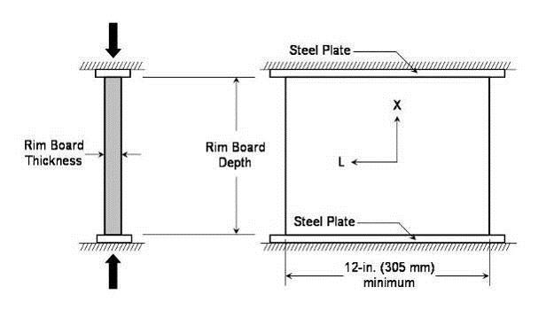
  • The minimum specimen length shall be 12 inches (305 mm) and tested as a stand-alone column, as shown in Figure 1.

(B) Test Method

  • Stand specimen on edge (no lateral supports) and load with a uniform compression load as rim board would be loaded when installed in a structure (in the X direction when loaded in the L-X plane, Figure 2).
  • Record cross head position versus load, at least every 0.01 inches (0.3 mm).
  • Apply preload of not more than 10% of anticipated maximum load.
  • Load to failure at a uniform rate so that failure occurs within two (2) minutes.
  • Record the load at a displacement of 0.06 inches (1.5 mm) and at failure.

(C) Performance Criteria

  • Calculate the mean test value for vertical uniform load transfer (in lbf/ft units) as the lesser of:
    1. the average load of all ten (10) specimens at 0.06 inches (1.5 mm) displacement times 3 and divided by the length of rim board; or
    2. the average load at failure of all ten (10) specimens divided by rim board length
  • The mean test value for vertical uniform load transfer shall meet the criteria in Table 1.

3.2.2 Lateral Load Transfer (Horizontal Shear)

(A) Test Specimens

  • Test a minimum of ten (10) specimens for each thickness of rim board at the maximum desired depth for each thickness.
  • Test assembly shall consist of rim board, I-joists, and sheathing and sill plates as shown in Figure 3, and of the dimensions and construction specified in Tables 3a or 3b.
  • Nailing schedules shall follow the requirements given in Table 4 and in this section of the standard. Note that there are different nailing configurations for product approval in the US or Canada.
  • The first and last nails between sheathing and rim board (edge nails) shall be 3 inches (76 mm) from each rim board end. Nails between sheathing and I-joist shall be 3 inches (76 mm) from each I-joist end. The first and last toe nails between the rim board and sill plate shall be at least 3 inches (76 mm) from each rim board end.
  • When testing rim boards for approval in Canada, a minimum of 3 82mm nails shall be installed through the sill plate of the wall above into the rim board, to verify the risk of splitting. The following conditions apply:
    • Half of the specimens shall have the bottom plate nail centered between the subfloor/rim board nails.
    • The remaining specimens shall have the 82 mm nails installed within 10 mm of the subfloor/rim board nails.
    • No nails shall be installed within 75mm of the end of the assembly.
    • All assemblies shall contain the same number of nails.
  • Assembly joist spacing shall not be less than 24 inches (610 mm).
  • Fabricate the assembly at least 12 hours before testing.

(B) Test Method

  • Apply loads through the sill plate while the sheathing reacts through full-width bearing, or vice versa.
  • To avoid overturning, vertical restraints or similar devices may be used as long as they do not interfere with the lateral deformation of the assembly in the direction parallel to the loading.
  • Measure assembly deformations along the entire length of the rim board based on the relative lateral displacements between the sill plate and sheathing. If any, isolate vertical displacements caused by overturning forces. Record load and deformation at equal load increments.
  • Rate of loading shall not exceed 450 lbf (2003 N) per minute.
  • No preload shall be applied. Load the assembly to failure or 0.4-inch (10 mm) lateral deformation, whichever occurs first. Record the load.

(C) Performance Criteria

  • Calculate the average recorded load of all ten (10) test specimens and divide by the tested rim board length, in [lbf/ft] units. The mean test value for lateral load transfer shall meet the criteria in Table 1.

3.2.3 Concentrated Load Transfer

(A) Test Specimens

  • Testing is only required when the rim board depth exceeds 16 inches (403 mm)
  • Test a minimum of ten (10) specimens, with a length of 16 inches (403 mm) as a stand-alone column

(B) Test Method

  • Test the specimens per section 3.2.1 (B) except apply the concentrated load through a 4.5-inch-long (115 mm) steel bar, with a minimum thickness of 0.50 inch (12.7 mm), and a width of at least equal to the rim board thickness. Center the steel bar on the 16-inch (403 mm) length of the test specimen.
  • Load to failure, recording the load at a displacement of 0.06 inches (1.6 mm) and at failure.

(C) Performance Criteria

  • Calculate the mean test value for concentrated load transfer as the average recorded load of all ten (10) test specimens at failure, or the average load of all ten (10) specimens at 0.06 inches (1.5 mm) displacement times 3, whichever is less, in [lbf] units.
  • The mean test value for concentrated load transfer shall meet the criteria in Table 2.

3.2.4 Edgewise Bending

(A) Test Specimens

  • Testing is only required for OSB and composite veneer/OSB rim board.
  • Test twenty-eight (28) specimens with a depth of 2 inches (51 mm) and a test span of 33 inches (838 mm) for each thickness shall be prepared in accordance with ASTM D 4761, Sections 6-11.
  • Specimens shall be stored indoors for at least 5 days prior to testing.

(B) Test Method

  • Specimens shall be tested in accordance with ASTM D 4761, Sections 6 through 11 (Bending Edge-Wise), with the exception that the load shall be applied mid-span (center-point loading).

(C) Performance Criteria

  • Calculate the mean value for modulus of elasticity and the characteristic value (fifth percentile with 75% confidence) for modulus of rupture. The calculated values for edgewise bending shall meet the criteria in Table 2.

3.2.5 Edgewise Shear

(A) Test Specimens

  • Testing is only required for OSB and composite veneer/OSB rim board.
  • Test twenty-eight (28) specimens for each thickness of rim board, at the maximum desired depth in accordance with ASTM D 5456, Section 6.5.5.
  • Specimens shall be stored indoors for at least 5 days prior to testing.

(B) Test Method

  • Specimens shall be tested in accordance with ASTM D 5456, Section 6.5.5.

(C) Performance Criteria

  • Calculate the characteristic value (fifth percentile with 75% confidence) for shear strength. The value for edgewise shear shall meet the criteria in Table 2.

3.2.6 Edgewise Compression

(A) Test Specimens

  • Testing is only required for OSB and composite veneer/OSB rim board.
  • Test twenty-eight (28) specimens for each thickness of rim board, at the maximum desired depth in accordance with ASTM D 5456, Section 6.5.4.
  • Specimens shall be stored indoors for at least 5 days prior to testing.

(B) Test Method

  • Specimens shall be tested in accordance with ASTM D 5456, Section 6.5.4.

(C) Performance Criteria

  • Calculate the mean value for compressive strength. The value for edgewise compression shall meet the criteria in Table 2.

3.3 Fastener Performance Testing and Criteria

3.3.1 Lag Screw

(A) Test Specimens

  • Test a minimum of ten (10) specimens for each thickness of rim board at the maximum desired depth for each thickness.
  • Prepare the specimens according to the assembly and component dimensions in Figure 4. Insert wax paper between the ledger and sheathing to minimize friction.
  • Use a ½-inch-diameter (12.7 mm) lag screw (ANSI/ASME B18.2.1) and washer in the assembly.
  • The ledger shall be nominal 2" x 6" SPF lumber.
  • Bore a clearance hole and 5/16-inch lead hole according to the guidelines provided in the 2012 NDS.
  • Fabricate the assembly at least 12 hours before testing.

(B) Test Method

  • Apply the load through the ledger while the rim board and sheathing react through full-width bearing, or vice versa.
  • Record load and deformation at equal load increments.
  • Rate of loading shall not exceed 0.1 inch (2.5 mm) per minute.
  • No preload shall be applied. Load the assembly to failure or 0.6-inch (15 mm) displacement, whichever occurs first. Record the load.

(C) Performance Criteria

  • Calculate the average recorded load of all ten (10) test specimens. The mean test value for lag screw withdrawal shall meet the criteria in Table 1.
Table 1. Required Mean Test Values1,2
Rim Board Grade Minimum thickness (inch) H (lbf/ft) V (lbf/ft) Z (lbf) P (lbf)
d ≤ 24 d ≤ 16 16 ≤ d ≤ 24 D ≤ 24 d ≤ 24
Standard150599004950120010,500
1-1/850513,2009000140010,500
Performance1N/A3
1-1/856014,5509600140010,500

For SI: 1 lb/ft = 14.594 N/m; 1 lbs = 4.448 N; 1 inch = 25.4 mm.
1. Gross adjustment factors provided in Appendix 1 for determining allowable design values.
2. H is horizontal shear load transfer; V is bearing (vertical) load; Z is lateral resistance of ½-inch diameter lag screw; and P is concentrated vertical load.
3. The minimum thickness for Performance grade rim board is 1-1/8 inch.

Table 2. Required Edgewise Values1,2
Grade fbe (lbf/in²) Ee (lbf/in²) fve (lbf/in²) Fc⊥e (lbf/in²)
Standard, Performance2070580,000850920

For SI: 1 lb/in² = 6.895 kPa.
1. All tests are loaded edgewise. fbe is edgewise modulus of rupture, Ee is edgewise modulus of elasticity, fve is edgewise shear, and Fc⊥e is edgewise compression perpendicular to grain at 0.04-inch deformation.
2. Values are applicable to standard-term duration (10 years), and can be adjusted for other load durations in accordance with applicable design codes (except for edgewise modulus of elasticity and compression perpendicular to grain).

Table 3a. Dimensions of Material Used to Prepare Test Assembly – US requirements
ComponentThicknessDepth or WidthLength
Rim boardAs required for each applicable test that utilizes the assemblyAs required for each applicable test that utilizes the assemblyMinimum 36 inch
I-joist1Maximum 1¾ inchMinimum 9¼ inch12 inch
SheathingMinimum 7/16 inch OSB12 inchMinimum 39 inch
Sill Plate (spruce-pine-fir grade)Nominal 2 inch lumberNominal 4 inch lumberMinimum 39 inch

For SI conversions, 1 inch = 25.4 mm. 1. Part of assembly construction (not rim board).

Table 3b. Dimensions of Material Used to Prepare Test Assembly – Canadian requirements
ComponentThicknessDepth or WidthLength
Rim boardMinimum of 25.4 mmMaximum of 600 mm900 mm
I-joist1Maximum 38 mm flangeMaximum of 600 mm300 mm
Sheathing15.8 mm300 mmMinimum of 975 mm
Sill Plate (spruce-pine-fir grade)38 mm89 mmMinimum of 975 mm
Table 4. Nailing Schedule for Preparation of Test Assembly
Connected ElementsFastener Specification and Spacing1,2 – USFastener Specification and Spacing2,3,4 – Canada
Sheathing to rim board and joist8d nails, spaced 6 inches on center51mm nails spaced 150mm on center
Bottom plate (from above) through subfloor to rim board2Not applicable82 mm nails spaced 400 mm on center
Rim board to sill plate8d nails, spaced 6 inch on centerToe-nail two (2) 63.5 mm nails through joist into sill plate, spaced 150mm on center
I-joist to sill plateUse 2 8d nailsUse two (2) 63.5 mm nails
Rim board to I-joistUse 2 8d nailsUse two (2) 63.5 mm nails

1. Box nails. 2. Alternative nailing schedules may be specified as long as they meet the minimum requirements. 3. Common or spiral nails as per the National Building Code of Canada. 4. Nails through bottom plate (from wall above) must be used when testing rim board for approval in Canada and are used to verify the risk of splitting.

3.4 Durability and Physical Properties Testing and Criteria

3.4.1 Edge Nailing Durability

(A) Test Specimens

  • A minimum of three (3) assemblies shall be tested for each rim board thickness and depth combination tested in accordance with sections 3.2 through 3.3.
  • The full size rim board specimens shall be conditioned in accordance with either ASTM D 1037 Section 23 (24-hour water soak) or an equivalent conditioning method.
  • Test assembly shall consist of rim board, I-joists, sheathing and sill plate as shown in Figure 3, and comply with the dimensions and construction specified in Tables 3a or 3b. The test assembly shall be built with wet rim board.
  • Nailing schedules shall follow the requirements given in Table 4. The first and last nails between sheathing and rim board (edge nails) shall be 3 inches (76 mm) from each rim board end. Nails between sheathing and I-joist shall be 3 inches (76 mm) from each I-joist end. The first and last toe nails between the rim board and sill plate shall be at least 3 inches (76 mm) from the end of each rim board.
  • Assembly joist spacing shall not be less than 24 inches (610 mm).
  • The assembly shall be fabricated at least 12 hours before testing.

(B) Test Method

  • Before testing, the rim board assembly shall be redried to a moisture content between 8 and 12 percent.
  • Apply loads through the sill plate while the sheathing reacts through full-width bearing, or vice versa.
  • To avoid overturning, vertical restraints or similar devices may be used as long as they do not interfere with the lateral deformation of the assembly in the direction parallel to the loading.
  • Measure assembly deformations along the entire length of the rim board based on the relative lateral displacements between the sill plate and sheathing. If any, isolate vertical displacements caused by overturning forces. Record load and deformation at equal load increments.
  • Rate of loading shall not exceed 450 lbf (2003 N) per minute.
  • No preload shall be applied. Load the assembly to failure or 0.4-inch (10 mm) lateral deformation, whichever occurs first. Record the load.

(C) Performance Criteria

  • Calculate the average recorded load and divide by the rim board length, in [lbf/ft] units. The product fails if the calculation is less than 75% of the average recorded load in Section 3.2.2 (C).

3.4.2 Glue Bond Durability

  • Sample from each rim board thickness and depth combination tested in accordance with sections 3.2 through 3.3.
  • For OSB and composite veneer/OSB rim board, 20 samples (one specimen per panel) shall be evaluated for single cycle (wet/redry) bending strength (parallel to the long axis of the panel) according to the procedures of PS 2 Section 7.6 after cycling according to PS 2 Section 7.16 and shall meet the tabulated values in PS 2 Table 7.
  • Structural plywood rim board shall meet the glue bond requirements of PS 1.

3.4.3 Thickness Swell

(A) Test Specimens

  • Testing is only required for OSB and composite veneer/OSB rim board.
  • Test a minimum of 5 panels (at least 5 specimens per panel for a total of 25 specimens) from each rim board thickness and depth combination tested in accordance with sections 3.2 through 3.3.
  • All specimens shall be 5.9 inches by 5.9 inches (150 mm by 150 mm).

(B) Test Method

  • Evaluate in accordance with the 24-hour water soak method of ASTM D 1037.

(C) Performance Criteria

  • No individual value may exceed 12 percent, and the average calculated thickness swell for all specimens shall not exceed 10 percent.

3.4.4 Moisture Content

(A) Test Specimens

  • Testing is only required for OSB and composite veneer/OSB rim board.
  • 20 samples (one specimen per panel with a dimension of 5.9 inches by 5.9 inches [150 mm by 150 mm]) shall be tested from each rim board thickness and depth combination tested in accordance with sections 3.2 through 3.3.

(B) Test Method

  • Evaluate for moisture content according to the procedures in ASTM D 4442.

(C) Performance Criteria

  • No individual moisture content value shall exceed 16%.

3.5 Control Value

3.5.1 Control values for rim board manufactured from structural-use panels

When rim board is manufactured from structural use panels such as plywood, OSB or other similar materials, control values and specifications stemming from the product standards must be established as follows.

(A) Rim board based on OSB and composite veneer/OSB panels (PS 2-type panels)

A mill specification with control values shall be developed in accordance with the following requirements using the same panels for each thickness evaluated in Sections 3.2 through 3.4:

  • Small-specimen-bending dry control values shall be developed in accordance with PS 2 Section 6.3.2.2. Twenty samples (of at least 2 specimens) taken from at least 10 panels shall be evaluated for dry bending strength and stiffness (parallel and perpendicular to the long axis of the panel) according to the procedures of PS 2 Section 7.6.
  • Bond performance (small-specimen-bending wet/redry) control values shall be developed in accordance with PS 2 Section 6.3.4.1 or based on the tabulated values in PS 2 Table 7. Twenty samples (one specimen per panel) shall be evaluated for single cycle (wet/redry) bending strength (parallel to the long axis of the panel) according to the procedures of PS 2 Section 7.6 after cycling according to PS 2 Section 7.16.
  • Density control values shall be established as the mean density less 2.1 standard deviations. Twenty samples (one specimen per panel with a dimension of 6 inches by 6 inches [150 cm by 150 cm]) shall be evaluated for density according to the procedures in ASTM D 2395. The weight and volume at typical manufacturing environmental conditions shall be used to establish the density control value.
  • Internal bond control values shall be established as the mean internal bond less 2.1 standard deviations. Twenty samples (5 specimens per panel) shall be evaluated for internal bond according to the procedures in ASTM D 1037.

(B) Rim board based on structural plywood

A mill specification for each rim board thickness evaluated in Sections 3.2 through 3.4 shall be developed for species, thickness, and panel grade in accordance with PS 1.

3.5.2 Control values for rim board manufactured from structural composite lumber

Control values for oriented strand lumber (OSL), laminated strand lumber (LSL), laminated veneer lumber (LVL), and other similar structural composite lumber products shall be established in accordance with ASTM D 5456.

4. Quality Control

In order for a manufacturer to use the TECO TESTED® certification mark, it must agree to follow TECO's quality control policies in this section and as referenced.

4.1 Monitoring rim board performance by the manufacturer

A manufacturer of certified rim board shall develop a quality control manual that satisfies the requirements of the TECO Inspection Procedure – SUP Sections 3.2.1 and 3.2.2. The QC manual shall establish the methods the manufacturer will follow to maintain conformance with the mill specification and control values established according to Section 3.5 and maintain performance levels at or above the design capacities. Certified rim board shall be manufactured in accordance with the QC manual.

4.2 Periodic quality system auditing by TECO

Manufacturers of TECO certified rim board shall be audited a minimum of four times per year, approximately quarterly, for operation in accordance with their quality control manual. Audit frequencies shall be assigned in accordance with TECO Inspection Procedure – SUP Sections 3.2.3 and 4.1.

4.3 Periodic testing by TECO

TECO will conduct periodic product testing for evaluation against requirements given in Sections 3.2 through 3.4. The frequency, not to exceed quarterly, and type of testing will depend on several factors including TECO quality system audit findings, product history, variability within the product, and production volume.

5. Labeling

TECO certified rim board must be identified with the following information:

  • Name of the manufacturer or the TECO mill number (posted on TECO's web site);
  • TECO's registered Certification Mark;
  • Grade of the rim board;
  • Performance Category;
  • Thickness; and
  • The RB 133 standard.

Example gradestamps are presented in Figure 5.

MILL No
TECO
TESTED
1 CATEGORY
STANDARD
RIM BOARD
RB133

THICKNESS 0.950 IN
MILL No
TECO
TESTED
1-1/8 CATEGORY
PERFORMANCE
RIM BOARD
RB133

THICKNESS 1.069 IN
Figure 5. Example Gradestamps for TECO certified rim board.

Appendix 1 — Calculation of Allowable Stress Design Values

Allowable Design Capacities

Allowable design capacities (F) are derived by dividing the population characteristic ultimate load values by adjustment factors that account for safety and probability of failure levels used for design. The population characteristic value commonly used for structural wood products is the 5th percentile at 75% confidence, and the adjustment factor of 2.1 is commonly used for strength properties of structural wood products.

The general equation for calculating the allowable design capacity of wood products is:

F = P.05 / 2.1    [A-1]

Where F = allowable property for an estimated 10-year load duration; P.05 = Characteristic value, equals the lower 5th percentile of test data (10-minute duration of load); 2.1 = Adjustment factor that converts Characteristic Value to Allowable Value. The adjustment factor includes a 10-year duration of load factor of 1.6 and a safety factor of 1.3.

In section 3, qualification testing and performance requirements are based on small sample sizes (n), and involve calculation of the sample mean ultimate load (p.50). To determine allowable load from mean values from qualification test data, the relationship is:

F = P.50 / X    [A-2]

where X = gross adjustment factor relating allowable load (F) to population average ultimate load (P.50). Setting equations [A-1] and [A-2] equal:

P.05 / 2.1 = P.50 / X    [A-3]

Using the relationship between population mean and population 5th percentile:

P.05 = P.50 (1 − 1.645 · COV)    [A-4]

where 1.645 = the population one-sided tolerance limit for calculating 5th percentile assuming large sample size and normal distribution; COV = population coefficient of variation. Substituting [A-4] into [A-3]:

P.50 (1 − 1.645 · COV) / 2.1 = P.50 / X    [A-5]

Solving for X:

X = 2.1 / (1 − 1.645 · COV)    [A-6]

Because performance tests in section 3 are based on small sample sizes, equation [A-6] is modified to accept a one-sided tolerance limit for small sample sizes. The resulting gross adjustment factor equation is:

X = 2.1 / (1 − k.05,.75,n · COV)    [A-7]

where k.05,.75 = 5th percentile at 75% confidence one-sided tolerance limit for sample size n (ASTM D2915, Table 3).

Substitution of sample mean ultimate load (p.50) and equation [A-7] into equation [A-2] results in equation [A-8]. Note that coefficient of variation for small sample sizes would be large, and would result in an overly-conservative calculated allowable property (F). For this reason, the population coefficient of variation (COV) remains in equation [A-4]. When using performance test results on smaller sample sizes:

F = p.5 / X    [A-8]

Table A1-1 provides values needed for determining the adjustment factor X, for calculating allowable properties using section 3 performance test results. Determine the capacity as the mean test value divided by Gross Adjust Factor, and is applicable to a shallower rim board of the same thickness and species combination. Table A1-2 presents the minimum Allowable Stress Design Values for rim boards qualified to this standard.

Table A1-1. Adjustment factors and sample statistics for determining allowable properties from performance test results.
Allowable PropertyGross Adjustment Factor, XSample size (n)k.05,.75,nAssumed Population COVAdjustment factor, C
Vertical Uniform Load Transfer (V) (§3.2.1)3.0102.1040.142.1
Lateral Load Transfer (H)1 (§3.2.2)2.8102.1040.123.0
Concentrated Load Transfer (P) (§3.2.3)3.0102.1040.142.1
Edgewise Bending (F) (§3.2.4)3.452281.8790.212.1
½" dia. Lag Screw Lateral Resistance3 (Z) (§3.3.1)4.0102.1040.123.0

1. H is a wood-framed system, however, assumed COV is for rim board product. Safety Factor is a calculated value that results in a gross adjustment factor of 3.0.
2. Note that the Gross Adjustment Factor (X) incorporates adjustment factors for volume (1.45), center-point loading (1.08), and moisture (1.05).
3. Capacities for the following items shall be determined according to ICC-ES AC 47, or the NDS, as applicable: connection of the top edge of the rim board to the building diaphragm; attaching the rim board to the wall plate below; attaching the rim board to the I-joists; attaching the exterior siding to the rim board; attaching an exterior deck ledger.

Table A1-2. Allowable stress design values for TECO rim board.
Rim Board GradeMinimum thickness (in) H1 (lb/ft)V1 (lb/ft)Z1 (lb)P1 (lb)
d ≤ 24D ≤ 1616 ≤ d ≤ 24D ≤ 24d ≤ 24
Standard11803,3001,6503003,500
1⅛1804,4003,0003503,500
Performance1N/A2
1⅛2004,8503,2003503,500

1. H is horizontal shear load transfer; V is bearing (vertical) load; Z is lateral resistance of ½-in. diameter lag screw; and P is concentrated vertical load capacity.

Appendix 2 — Alternative Test Method

Alternate method for Vertical Uniform Load Transfer Capacity

(A) Test Specimens

  • Prepare test specimens in accordance with section 3.2.2 (A) except the sill plate is not required for the assembly. To avoid direct bearing on the I-joists, an end notch of approximately ½ inch (12.7 mm) in depth and at least 3-1/2 (89 mm) inches in length shall be provided on the flange (bottom side of assembly only).

(B) Test Method

  • Apply loads through the sill plate while the sheathing reacts through full-width bearing, or vice versa. No lateral supports shall be used for the testing assembly.
  • Record cross head position versus load, at least every 0.01 inches (0.3 mm).
  • Load should be applied at a uniform rate and failure should occur within two (2) minutes.
  • Apply preload of not more than 10% of anticipated maximum load. Load to failure. Record the load at failure and the load at displacement of 0.06 inches.

(C) Criteria

  • Calculate the vertical uniform load transfer mean test value as the average recorded load of all ten (10) test specimens divided by the tested rim board length, or the average load at 0.06-inches displacement times 3 divided by the length of rim board, whichever is less, in [lbf/ft] units. The vertical uniform load transfer mean test value shall meet the criteria in Table 1.

Appendix 3 — Conversion of Allowable Stress Design Values to Limit States Design

When appropriate – and for all use in Canada – design of structures shall follow the principles of Limit States Design (LSD). It is acceptable to use a simple mathematical calculation to convert Allowable Stress Design (ASD) values to appropriate factored resistances for LSD applications.

The following sections explain the conversion of the ASD values from Table A1-2 and are harmonized with the requirements of the Canadian Construction Materials Center (CCMC), which issues proprietary evaluation reports for building products used in Canada.

1. Horizontal Load Capacities (H)

This conversion follows the same procedures used in clause 9 of CSA O86-01, where ASD values for shear walls were converted to factored resistances for LSD.

LSD: φKD,LSDHLSD,std term ≥ αQQ   (A3-1)
ASD: HASD,short term ≥ Q   (A3-2)

Conditions: φ = resistance factor = 0.7 for shear walls; KD,LSD = LSD load duration factor of 1.15 for LSD short-term loading; αQ = LSD load factor of 1.5 for wind; Q = Applied load. From Equations A3-1 and A3-2:

φ HLSD,std term = [αQ/KD,LSD] HASD,short term = [1.5/1.15] HASD,short term = 1.304 HASD,short term

The conversion factor for the factored horizontal load capacities (φHLSD) is 1.304 but it is based on LSD standard term, not short term load duration.

2. Uniform Vertical Load Capacities (V)

LSD: φKD,LSDVLSD ≥ αDQD + αLQL   (A3-3)
ASD: KD,ASDVASD ≥ QD = QL   (A3-4)

Conditions: φ = resistance factor = 0.95 for compression members; KD,LSD = LSD load duration factor of 1.0 for standard-term loading; αD = LSD dead load factor of 1.25; αL = LSD live load factor of 1.5; KD,ASD = ASD load duration factor of 1.15 for snow load on roof. When calibrated to QL/QD = γ = 4.0 as in accordance with CSA O86:

φVLSD = (1.25 + 4×1.5) / (1.0×(1+4)) × 1.15 × VASD = 1.668 VASD

Due to the location of rim boards within a wall assembly, it is not required to include adjustments for the effects of relative humidity – consistent with CSA O86 – so the adjustment factor for the factored uniform vertical load capacities is 1.668.

3. Concentrated Vertical Load Capacities (P)

The conversion factor for the factored concentrated vertical load capacities (φPLSD) is the same as for factored uniform vertical load capacities (φVLSD) and is 1.668.

4. Lag Screw Capacities (Z)

The derivation of the lag screw conversion factor follows the same procedures as for factored uniform vertical load capacities. The conversion factor for lag screw capacities (φZLSD) is also 1.668.

Table A3-1. Converted, factored resistances of TECO rim board.
Rim Board GradeMinimum thickness (mm) φH1 (kN/m)φV1 (kN/m)φZ1 (kN)φP1 (kN)
d ≤ 610d ≤ 406406 ≤ d ≤ 610D ≤ 610d ≤ 610
Standard253.480.340.22.226.0
293.4107.173.02.626.0
Performance25N/A2
293.8118.177.92.626.0

1. H is horizontal shear load transfer; V is bearing (vertical) load; Z is lateral resistance of ½-in. diameter lag screw; and P is concentrated vertical load capacity.