
Who We Are
Ofrecemos servicios TIC para mejorar la seguridad contra incendios, la seguridad humana y la seguridad eléctrica a nivel global, garantizando el cumplimiento y reduciendo riesgos.

The design values in this document correspond with those published in the 2005 edition of the AF&PA American Wood Council's Allowable Stress Design (ASD)/LRFD Manual for Engineered Wood Construction. TECO has chosen to do so to provide harmony among users — architects, engineers, specifiers and the regulatory community. These are "Industry Recommended" values, but are not rigorously evaluated for on-going verification.
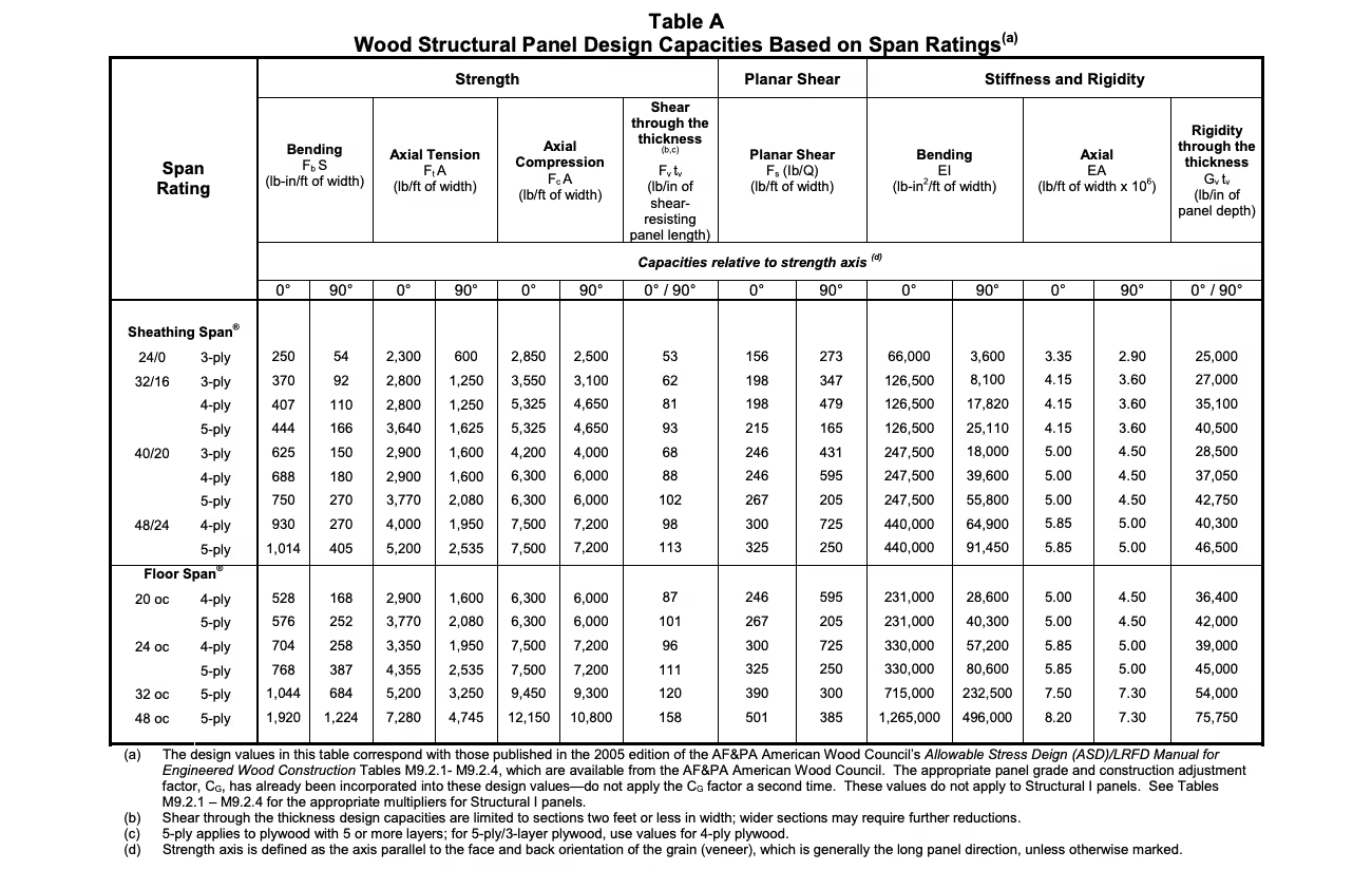
Load capacities, which are presented here for allowable stress design (ASD) (Table A), are applicable to plywood panels qualified in accordance with TECO test protocol. Nominal panel thickness (Table B) assists in calculation of geometric cross-sectional properties. The applicable section properties (Table C) can be divided into load capacity to determine design strength and stiffness. Load capacities in Table A are based on normal duration of load for untreated panels under dry conditions. Because these values are plywood-specific, the appropriate panel grade and construction adjustment factors, CG, have already been applied. Designers must be careful to avoid making the CG adjustments again.
Adjustment factors for other conditions are permitted in accordance with applicable code provisions. The National Design Specification for Wood Construction (NDS) provides guidance on the use of adjustment factors.
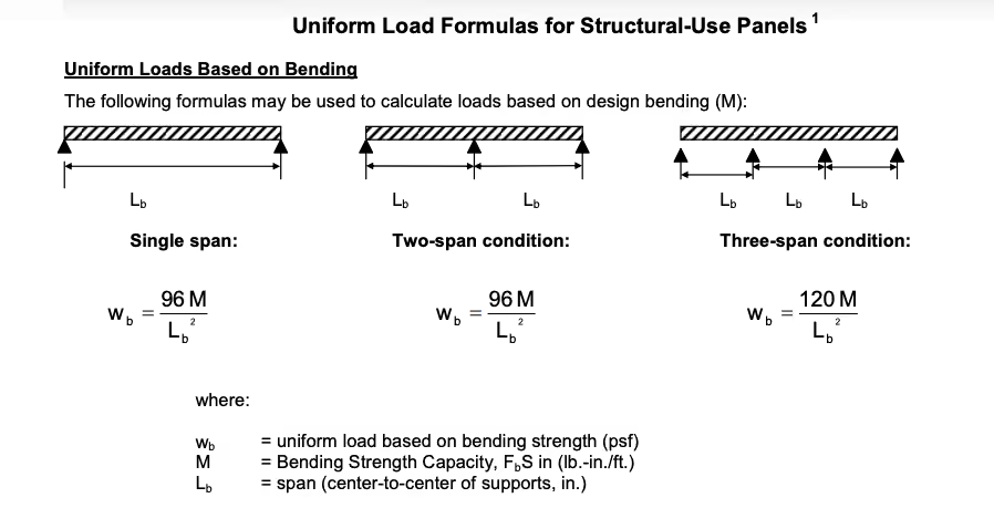
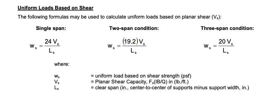
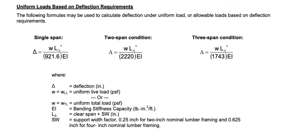
Methods presented in this section may be used to calculate uniform load capacity of structural-use panels in floor, roof and wall applications. The design capacities presented in Table A include the grade and construction factor, CG. Other applicable adjustment factors as specified in Section 9.3 of the 2005 edition of the ANSI/AF&PA NDS-2005, National Design Specifications (NDS) for Wood Construction ASD/LRFD and Section C9.3 of the 2005 Edition of the AF&PA American Wood Councils' Commentary National Design Specification (NDS) for Wood Construction ASD/LRFD, should be applied to the design capacities.
There are three possible span conditions to consider when computing the uniform load capacities of structural-use panels depending on the size and orientation of the panel and the spacing of the framing support members. These include single-span, two-span and three-span (see below). For normal framing practice and standard panel size (i.e., 4x8 foot), when the panel strength axis is perpendicular to framing supports, the three-span condition is used for support spacing up to and including 32 inches on center. Use the two-span condition for support spacing greater than 32 inches on center but no greater than 48 inches on center. When the panel strength axis is placed parallel to framing supports, the three-span condition is used for support spacing up to and including 16 inches on center. Use the two-span condition for support spacing greater than 16 inches but no greater than 24 inches on center. Use the single-span condition for support spacing greater than 24 inches on center.
The formulas presented are for computing uniform loads on structural-use panels applied over conventional framing. These equations are based on standard beam formulas altered to accept the mixed units. For support spacing less than 48 inches, nominal two-inch framing members are assumed. For support spacing 48 inches and greater, nominal four-inch framing members are assumed. Since the formulas assume that no blocking is used, the formulas are for one-way "beam" action rather than two-way "plate" action. The resulting loads are for the structural panels only and do not account for the design of the framing support members. The resulting loads calculated from the equations are assumed to apply to full size panels in standard sheathing applications. Considerations for concentrated loads should be made in compliance with local building codes and maximum span recommendations.
4x8 foot, 32/16, 4-ply, TECO SHEATHING SPAN® plywood panels are installed as roof sheathing over roof trusses (nominal 2 inch wide) spaced at 32 inches on-center. The panels are installed with the long panel direction (strength axis) perpendicular to the roof truss members. The job specifications indicate that the roof is to be designed to support a 20 psf snow load @ 1.15 load duration with an allowable live load deflection (wLL) of span/240 and an allowable total load deflection (wTL) of span/180. Determine if the specified panel will adequately meet these requirements.
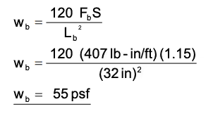
From Table A, the F b S (bending capacity) of a 32/16, 4-ply SHEATHING SPAN panel installed with the stress applied parallel to the strength axis is equal to 407 lb-in/ft of width. The C G factor (panel grade and construction factor) has already been applied to this capacity, but the load duration factor, C D , of 1.15 can also be applied for snow load. Since the trusses are spaced at 32 in. on center and the panels are oriented with their 8 ft dimension perpendicular to the framing, use the equation for the three-span condition.
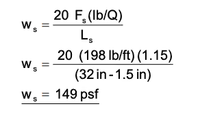
From Table A, the F s (Ib/Q), planar shear capacity, of a 32/16, 4-ply SHEATHING SPAN panel installed with the stress applied parallel to the strength axis is equal to 198 lb/ft of width. The C G factor (panel grade and construction factor) has already been applied to this capacity, but the load duration factor, C D , of 1.15 can also be applied for snow load.
From Table A, the EI (bending stiffness capacity) of a 32/16, 4-ply SHEATHING SPAN panel installed with the stress applied parallel to the strength axis is equal to 126,500 lb-in 2 /ft of width. The C G factor (panel grade and construction factor) has already been applied to this capacity. Notice that the load duration factor, C D does not apply to bending stiffness.
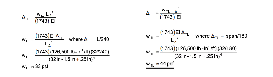
Based on the specifications for this design example, the design capacity of the 32/16, 4-ply SHEATHING SPAN plywood panels is controlled by bending stiffness. The 44 psf represents the maximum uniform load that can be applied to the panels before the deflection criterion of span/180 is exceeded. As long as the dead load of the roof system (i.e., weight of panels, shingles, etc.) does not exceed 24 psf (i.e. 44 psf total load – 20 psf snow load), the 32/16, 4-ply SHEATHING SPAN plywood will meet the design specifications for this project.